AUTOMATIC CAR CREEPER
BATTERY POWERED CREEPERS CAN COST THOUSANDS OF DOLLARS. So we decided to build an automotive creeper with less than a $300 budget.


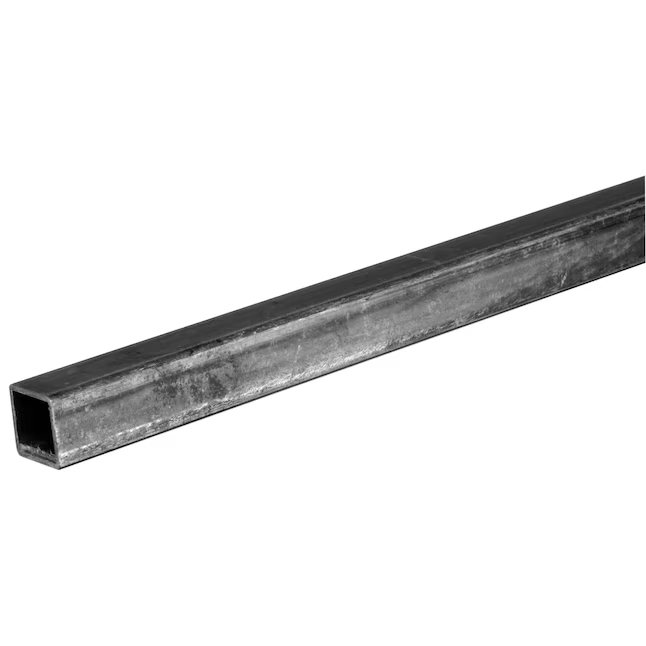
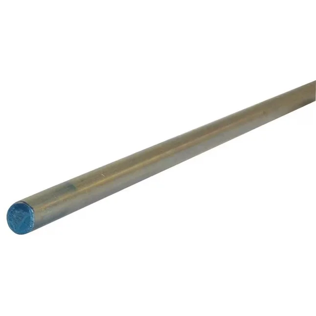
We started with a low-cost Harbor Freight automotive creeper with wheels and an adjustable headrest for the base. Other required parts include 3/4 inch steel tubing, 3/8 inch metal rod, pin/clips, a linear actuator, battery, dc-to-dc converter, and a toggle switch. Next up is putting it all together.
STEP 1: FRAME MODIFICATIONS
First, you'll need a way for the back portion of the seat to pivot forward. We cut 3/8 inch diameter holes at the base of the creeper and added a steel rod held by pins and clips. The steel tubing was cut down to two 4-foot pieces along with a set of 3/8 inch diameter holes which allowed the steel tubing to slide into the steel rod.
STEP 2: POWER COMPONENTS
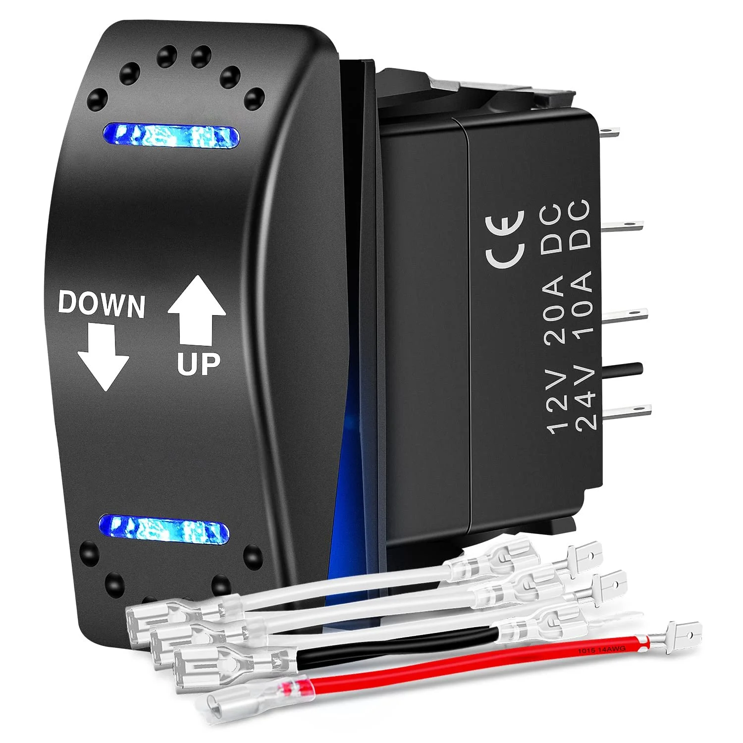
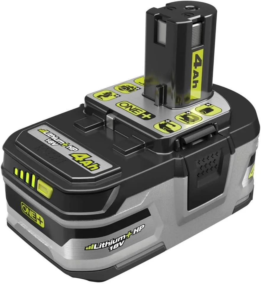
You’ll require a linear actuator to lift the back of the seat from the lying position. Additionally, you'll need a cordless battery, an adapter, an 18-volt to 12-volt DC converter, and a toggle switch to control the linear actuator. The battery connector goes to the 18v DC to DC input and the DC to DC output goes to the toggle switch. The toggle switch then gets wired to the 3000 N linear actuator.
STEP 3. REINFORCE THE CAR CREEPER
Once the two steel square tubes are able to pivot from the first steel rod, we reinforce the creeper with steel plates separating the steel square tubes by 13 inches. The steel plating was welded in place using our Eastwood MP140i with gasless flux.
STEP 4. SECONDARY PIVOT
Next, use the spare 2 feet of leftover square tubing for the next pivot. The 2ft square tubing connects to the 4ft square tubing at around 11 inches from the bottom of the 6ft square tubing. The tubing is held together using some pins and clips.
The back of the 4ft square tubing rests on the main car creeper frame by another steel rod which is mounted to the back of the 2ft square tubing.
STEP 5: LINEAR ACTUATOR MOUNT
The linear actuator will now be installed onto the rear steel rod with the included bracket which then connects to the back of the 4ft steel tubing. An additional 3/8 inch hole was cut into the bracket to allow it to be slightly angled. This will help push the seat up instead of outward.
STEP 6: MODIFY THE BRACKET
We had to modify the linear actuator bracket to lift the back of the seat before the linear actuator started to fully engage. This ensured that the linear actuator had a steeper angle to better lift instead of push outward. The mount was modified by welding two of the included linear actuator mounts together.
STEP 7: TESTING DIY CAR CREEPER
Now, for the moment of truth. We hooked up power to the actuator using our 18v Ryobi battery, laid down under the car, and pushed the switch. We started to lift off the ground with the automatic car creeper, but some of the flat steel bent. So we plan to change all the mounting points to square tubing soon.


